
Part 1: Introduction and Hardware Overview.
Advertised as an expansion board for CME UF master keyboards and introduced over 15 years ago, the nano is one of the lesser known Waldorf synths. Nevertheless, you can still buy a new nano from certain retailers. And it was only recently when this little device caught my attention again.
In fact, the nano is not even a Waldorf product, since at the time of its introduction in 2006, Waldorf’s resurrection from insolvency was still pending [read more about Waldorf’s history]. And it is not an editable synthesizer either. Shipped with plenty of presets, it only lets you temporarily tweak a few parameters. But you cannot you store your modifications or create completely new sounds.
This limitation, and the fact that it was targeted towards a narrow range of CME keyboard models might be among the most important reasons for the nano to never gain popularity. Last but not least, the microQ Phoenix edition and the especially the Blofeld which arrived in late 2007 made the nano look very unattractive. But hey, it’s not about looks and popularity here!
The official documentation was pretty sparse when it originally came out. And as of mid-2021, there is still almost no information available. So let’s dig deeper and change that, shall we?
About this series
Over the course of the next weeks I will explore the nano and share my insights with you. My main motivation here is curiosity and the desire to learn more about DSPs and the products of my favorite synth manufacturer.
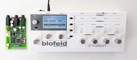
I have already analyzed the nano’s circuitry, studied tons of datasheets, and compared the nano to other Waldorf machines. Another outcome is a DIY project I called the “nano Pocket” – probably the world’s smallest sound module with Waldorf sound. More on that in Part II. Currently, I am investigating the capabilities of the nano’s synth engine. This will be subject of a later article.
What’s in the box?
To get more familiar with the nano, here is what you get if you buy one.
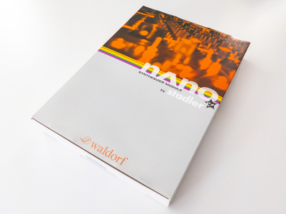
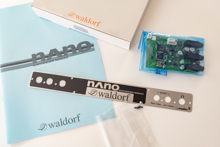
The nano comes in a surprisingly large box which can accommodate the wide rear panel for the CME UF keyboard, a printed A4 manual, and a generous amount of foam. The nano module itself is actually quite small (74mm x 114mm, including TRS jacks) but it’s pretty well equipped.
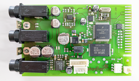
What’s on the board?
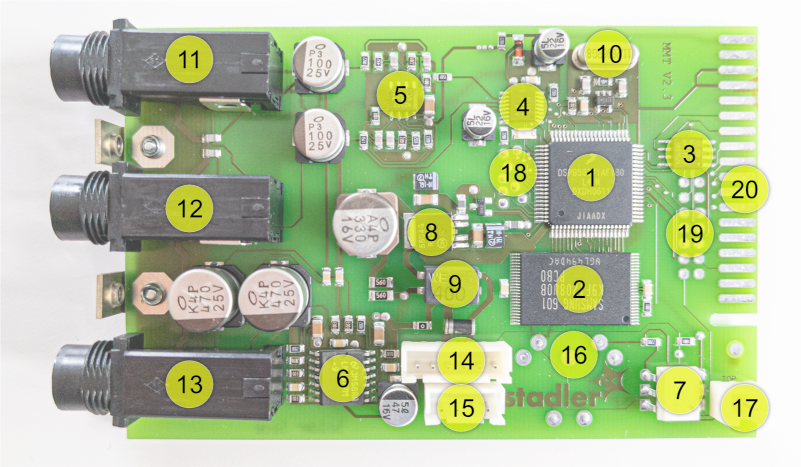
- DSP
- Flash memory
- Serial EEPROM
- Audio DAC
- Line amplifier
- Power amplifier for headphones
- Optocoupler for Midi input
- Voltage regulator
- Power supply choke
- Crystal oscillator
- Line out jack, right channel
- Line out jack, stereo out or left channel
- Headphone jack, stereo out
- Power supply and Midi input (low-voltage TTL)
- Power supply
- Footprint for 5‑pin Midi jack (opto-isolated)
- Midi input (opto-isolated)
- Test pads (undocumented)
- Debug connector (undocumented)
- Card edge connector (undocumented)
Connector Pinouts
| Connector | Pinout | Remarks |
|---|---|---|
(14) JST-XH‑6 connector: power supply / Midi input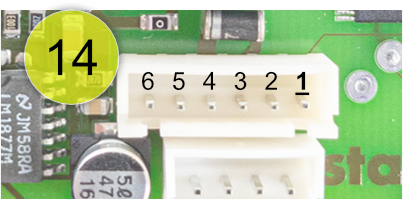 | 1: Midi in (3.3V low-voltage TTL, 5V tolerant)* 2: not connected 3: Ground 4: +12V 5: +12V 6: Ground | *: Caution: Pin is directly connected to the DSP. Protect from electrostatic discharge! |
(15) JST-XH‑4 connector: power supply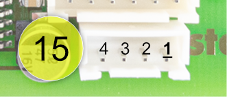 | 1: Ground 2: +12V 3: +12V 4: Ground | |
(16) Footprint for 5‑pin DIN jack: opto-isolated Midi input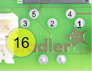 | 1: n/c 2: n/c 3: n/c 4: Vref 5: Midi in | Either use this connector or (17) if you want to use the nano with a Midi interface or Midi keyboard. |
(17) JST-XH‑2 connector: opto-isolated Midi input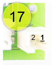 | 1: Vref 2: Midi in | Either use this connector or (16) if you want to use the nano with a Midi interface or Midi keyboard. |
A Proto-Blofeld and Development Board?
Little is known about the specifics of the nano. When interviewed by German Sound & Recording magazine, Stefan Stenzel pointed out that the nano is “related to the microQ […] but with functional limitations” and that they had been “using existing hardware and software components” [source: “Sound & Recording” 09.2006: nano test and interview with Stefan Stenzel]. I will cover the synth engine in a later article and try to find out more about it.
Here, I will focus on the hardware aspects. As it turns out, the nano is much closer to the Blofeld than to the microQ in this regard (see comparison table below and my Waldorf Synth Hardware page).
In hindsight, Stefan’s statement seems due to the fact that the the interview took place well before the Blofeld was announced.
To me, the nano appears to be an intermediate step, a Proof-of-Concept while designing a new cost-effective synth platform – a kind of “Proto-Blofeld” if you like. It is not unlikely that the nano had also served as a Waldorf-internal development board, having all these debug connectors which are not used with the CME UF keyboard.
Hardware Comparison
To better understand the nano’s position I have compared it against the microQ and the Blofeld.
| microQ (MQMB12B + MQBP12) | nano (MMT V2.3) | Blofeld (BFMB V1.41) | Blofeld, Blofeld Keyboard (BFMB V2.04) | |
|---|---|---|---|---|
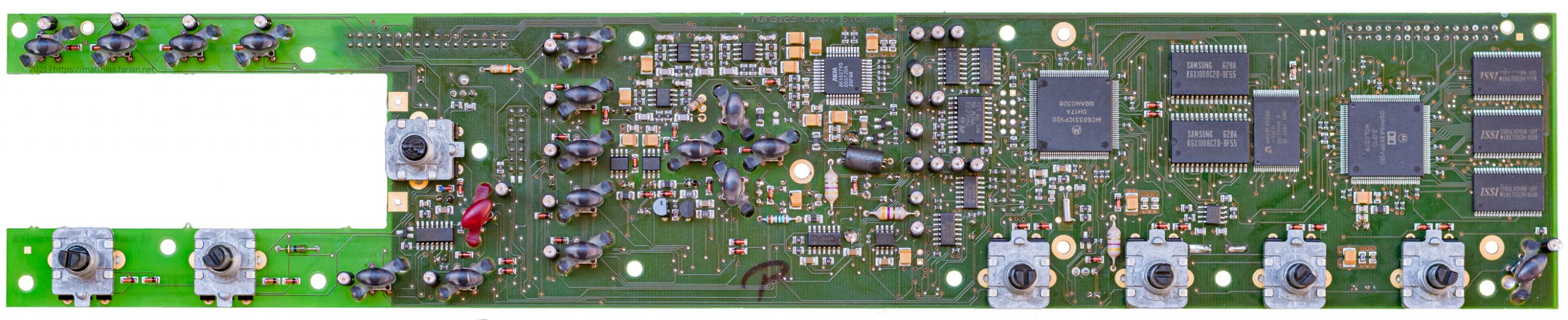 | 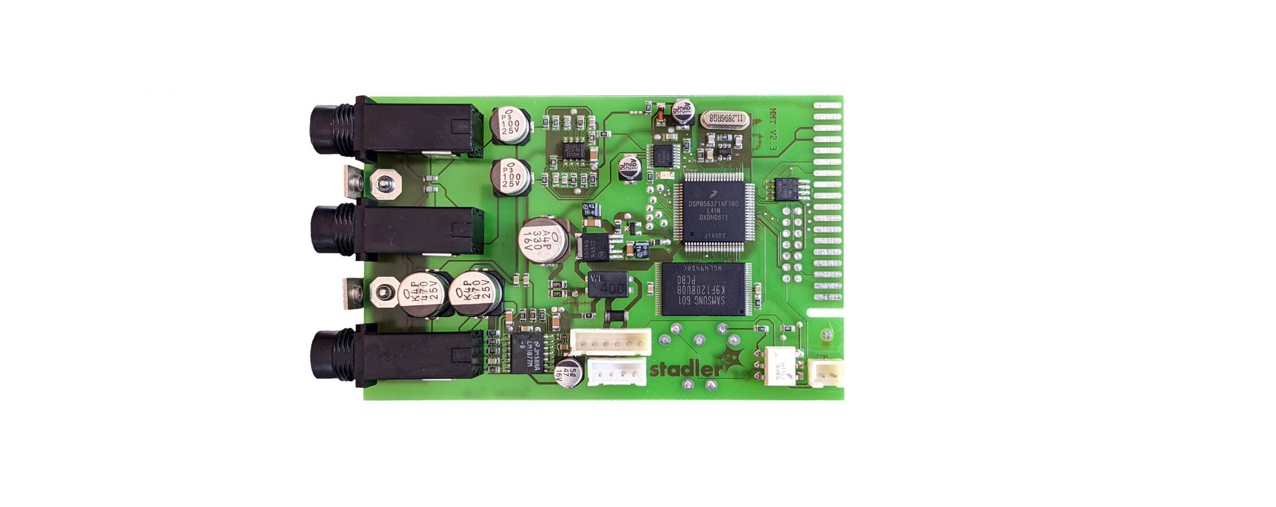 | 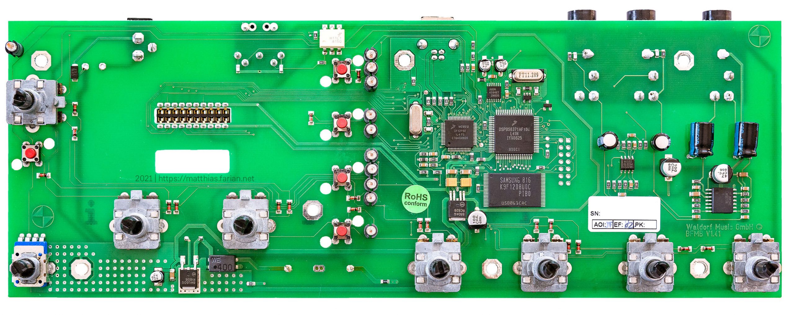 | 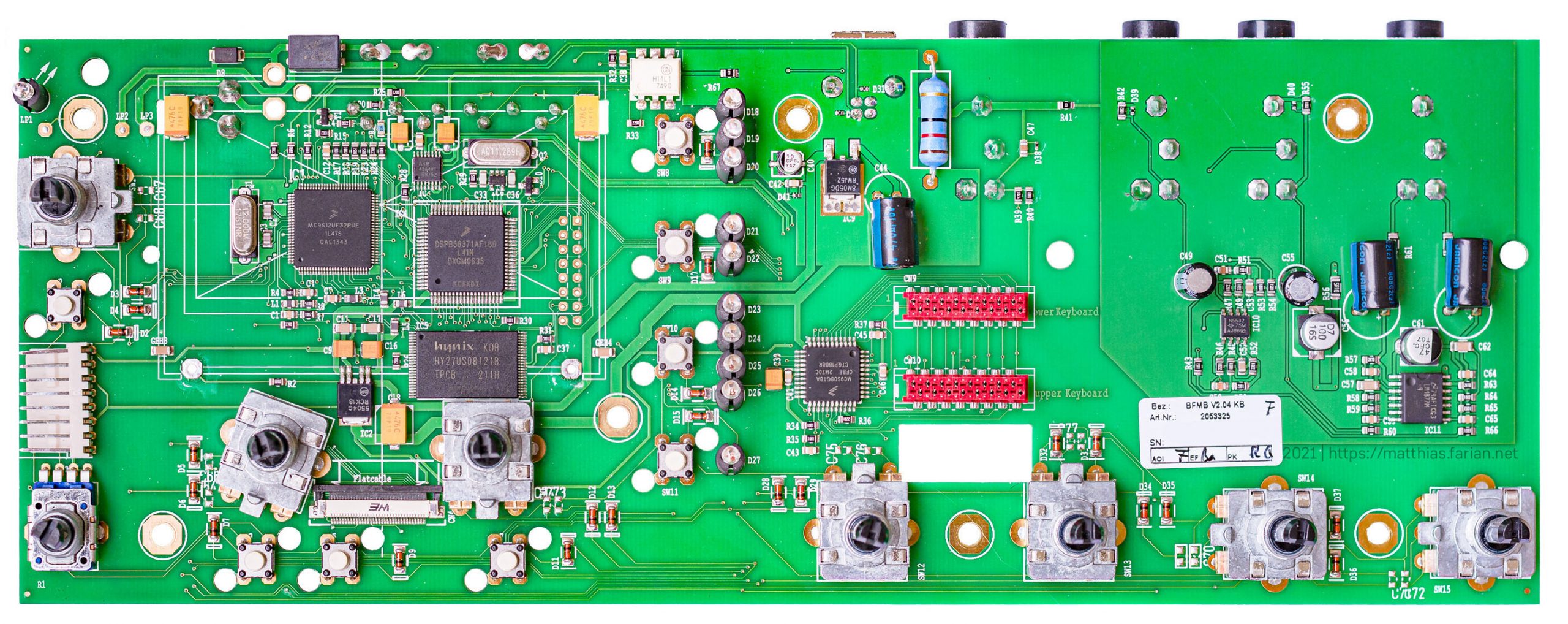 | |
| DSP | 1x DSPH56362 | 1x DSPB56731 | 1x DSPB56731 | 1x DSPB56731 |
| External DSP RAM | 3x 2 Mbit SRAM | n/a | n/a | n/a |
| Optional Expansion Board | 2 additional DSPs + RAM | n/a | n/a | n/a |
| Main MCU | MC68331CPV20 | n/a | MC9S12UF32PBE | MC9S12UF32PUE |
| External Main MCU RAM | 2x 1 Mbit SRAM | n/a | n/a | n/a |
| Non-volatile memory | 1x 4 Mbit Flash | 1x 512 Mbit NAND Flash 1x 256 Kbit serial EEPROM | 1x 512 Mbit NAND Flash | 1x 512 Mbit NAND Flash |
| Auxiliary MCU(s) | n/a | n/a | n/a | Blofeld Keyboard only: MC9S08GT8A |
| Sample Rate | 48 kHz | 44.1 kHz | 44.1 kHz | 44.1 kHz |
| Audio Outputs | 6 channels | 2 channels | 2 channels | 2 channels |
| Audio Input | yes (stereo input) | n/a | n/a | n/a |
| DAC | 1x AKM AK4527 Multi-Channel Codec for ADC and DAC | 1x AKM AK4384 2ch Delta Sigma DAC | 1x AKM AK4384 2ch Delta Sigma DAC | 1x AKM AK4384 2ch Delta Sigma DAC |
| ADC | Multi-Channel Codec for ADC and DAC (see above) | n/a | n/a | n/a |
| Line Amplifier | 3x NE5532 (one per stereo output) 1x TL072 (stereo input) | 1x NE5532 (stereo output) | 1x NE5532 (stereo output) | 1x NE5532 (stereo output) |
| Headphone Amplifier | LM8272MM | LM1877M | LM1877M | LM1877M |
For a more detailed comparison, please find the tables on my Waldorf Synth Hardware page.
Historically, Microwave II and Q based machines were built around general purpose Motorola chips from the mid and late 1990s:
- DSP56303 (Microwave II/XT/PC, early Q and Q Rack revisions)
- DSP56362 (microQ, later Q and Q Rack revisions)
- MC68331 MCUs
- Auxiliary PIC16 controllers (Microwave II/XT/PC, Q and Q Rack)
These chips only have little internal memory, so external memory was unavoidable for synth applications. RAM and Flash chips in the mid/late 1990s had low capacity and bulky packages. As a result, Waldorf’s synths typically consisted of a densely populated main board (with four copper layers) and multiple daughter boards for front panel, rear connectors, display. This all added to complexity and production costs.
In contrast, the DSP56371 used for the nano (and later also for Blofeld, Studiologic Sledge, and Hartmann 20) is specifically targeted towards audio applications. It is improved in memory capacity, clock speed, footprint, and power consumption. But it is not high-end and considerably stripped down in I/O (i.e. the ports formerly used by Waldorf for their expansion cards and external memory). As a consequence, certain limitations affecting a synth engine’s voice count and memory-intensive effects like delay or reverb are to be expected.
Ultimately, it allows for designing more streamlined and more economic products. The nano can be considered as a preview for what eventually became the Blofeld: a great sounding and inspiring synthesizer for the masses. A machine which is still in production and selling after almost 15 years – at approximately the same price point. In consumer electronics, especially in the synthesizer market, this is an outstanding achievement!
Part 2: »nano Pocket« – Ultra Portable Synth Module (DIY)
Concept and Objectives
- Portable with a form factor as small as possible – ideally have everything fit into a 2.5″ HDD case
- Simple user interface for selecting built-in sounds (requires micro controller, encoder, button, and a display)
- 5V supply from a power bank or USB charger, avoid special cables or voltages
- Midi input via standard 5‑pin DIN plug or 3.5mm-TRS to DIN adapter
- Keep existing 1/4″ line output connectors and internal amplification
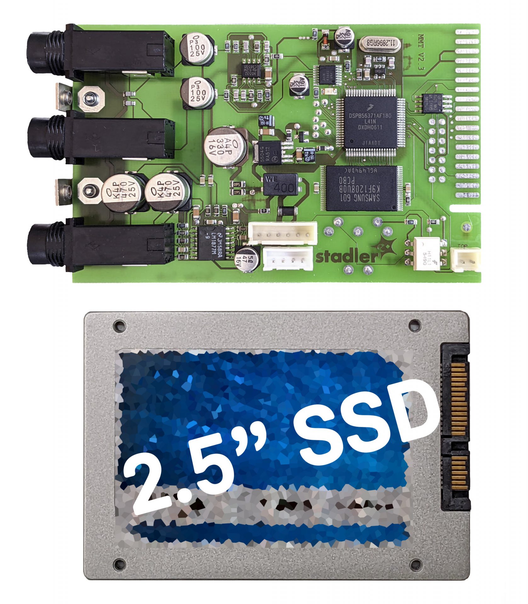
Suitable HDD enclosure: ICY BOX IB-256WP
- Sturdy aluminium body with plastic slide-in module
- Dimensions: 77mm x 113mm x 20mm (without silicone bumper)
- Internal PCB with USB–SATA adapter can be removed for gaining some extra room
Modifications
Freeing up Space on the PCB
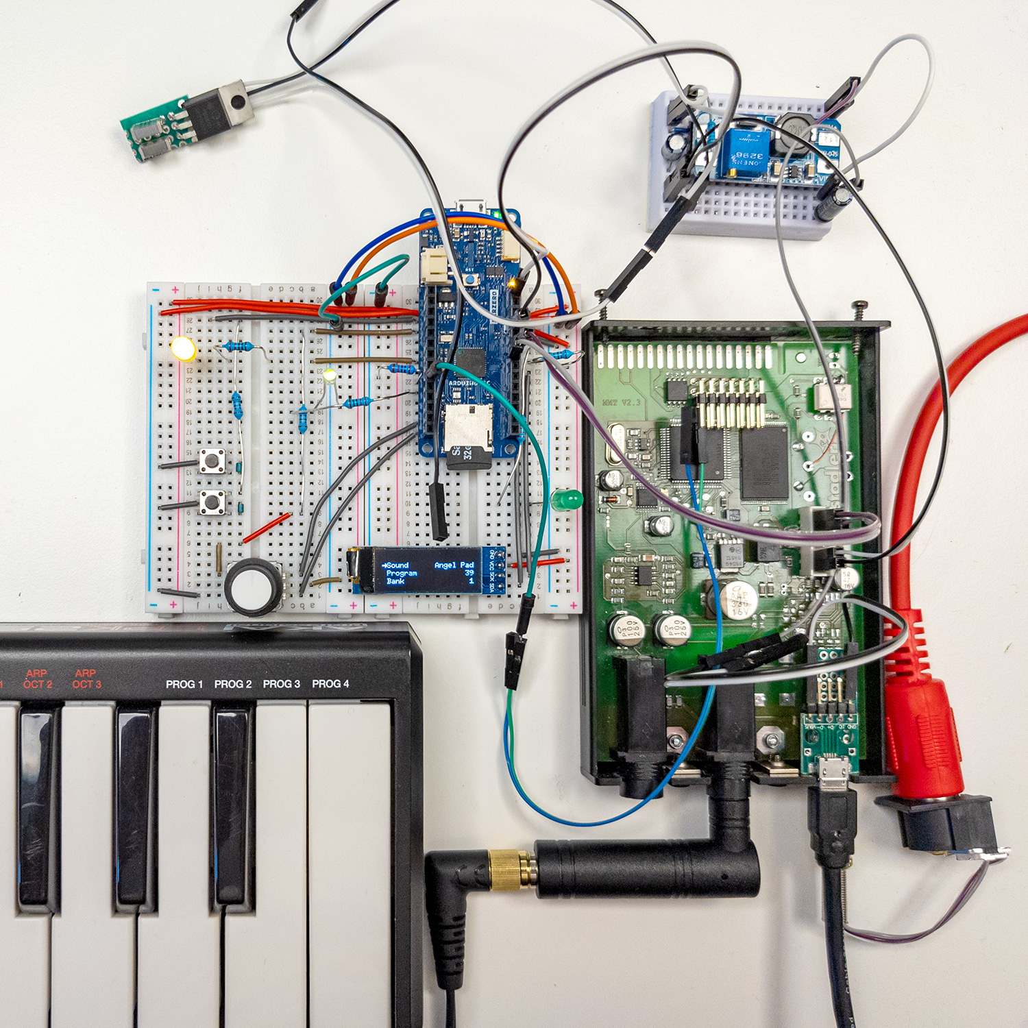
Power Supply
When connected CME UF keyboard, the nano is supplied by a single 12 V rail. While the Opamp and the Headphone Amplifier need this voltage for proper output levels, the rest of the active components only require 3.3 V (DSP: 3.3 V and 1.25 V).
In its original configuration, a common mode choke, two 56 Ohm resistors in parallel, and filter capacitors provide high frequency suppression. A dual linear voltage regulator then generates the required 3.3 V and 1.25 V. As a result, during idle operation, the nano converts about 0.9 W into heat in the power supply section alone. Since there no big copper area which could act as a heat sink, these components as well as the 330 µF electrolytic capacitor get very hot. Especially in case of the capacitor, this could result in accelerated aging.
For the »nano Pocket«, I made some modifications: A boost converter generates 12 V from 5 V. A 12 V supply is not necessary anymore and the »nano Pocket« can be powered by a USB charger or USB power bank. Even if the input voltage is at the lower limit of the USB specification (5 V – 10%), 12 V can be generated reliably. From the 12 V rail, a cheap MPS MP2307DN based buck converter (search for “HW 187” or “Mini-360” and read Dr. Gough’s article) generates 5 V for the dual linear regulator and the Arduino. There might be better alternatives but it certainly does its job.
At first glance it seems like unnecessary complexity step to boost 5 V up to 12 V and then step down to 5 V again. But it turned out to be necessary since with input voltages lower than 5 V, the linear regulator cannot reliably provide 3.3 V. For the DSP you want to ensure that a stable 3.3 V supply is available before the 1.25 V supply. Otherwise, there is the risk of a latch-up which can damage the chip which happened to me during my experiments.
Midi Signal Routing
User Interface
…
Coming up next
…
You must be logged in to post a comment.